Posted on

AGCO/Fendt 8300/8350 Series Combine Factory Service & Shop Manual


Pages from 63002095 M4 – AGCO-Fendt 8300-8350 Series Combine Workshop Manual


INSTANT DOWNLOAD


Complete workshop & service manual with electrical wiring diagrams for AGCO/Fendt 8300/8350 Series Combine. It’s the same service manual used by dealers that guaranteed to be fully functional and intact without any missing page.

This AGCO/Fendt 8300/8350 Series Combine service & repair manual (including maintenance, overhaul, disassembling & assembling, adjustment, tune-up, operation, inspecting, diagnostic & troubleshooting…) is divided into different sections. Each section covers a specific component or system with detailed illustrations. A table of contents is placed at the beginning of each section. Pages are easily found by category, and each page is expandable for great detail. The printer-ready PDF documents work like a charm on all kinds of devices.

FILELIST:
63002095 M4 – AGCO/Fendt 8300-8350 Series Combine Workshop Manual.pdf
63006340 M4 – AGCO/Fendt 8300-8350-Baureihe RTS Richtzeitliste (DE).pdf
D3150100 M10 – AGCO/Fendt 8300-8350 + Auto Level + Rotary Separator Operator’s Manual.pdf
D3151900 M1 – AGCO/Fendt 8300-8350, 8370P-8400P Series Combine Repair Time Schedule (RTS).pdf

EXCERPT:
Table of Contents
0 Introduction – Specifications
1 Cutting table
2 Reel
3 Main crop elevator
4 Threshing unit
5 Straw walkers
6 Shaker shoe – Fanning mill
7 Elevators
8 Engine
9 Unloading auger – Grain tank
10 Drive unit
11 Transmissions
12 Undercarriage
13 Cab
14 Hydraulics
15 Machine housing
16 Electrical system
17 Straw chopper
18 General assembly instructions
19 Miscellaneous data

12. Undercarriage
12.3 Gearbox – 4 gear ranges
12.3.1 Removal
1 . Dismount the traction wheels and chock up the machine on a secure and reliable support.
2. Drain off gear oil from the coupler housing.
3. Remove the locking bolt and push the bushings (A) towards the brake disc on both sides so that they are clear of the gearbox output shaft IBI.
4. Drain off gear oil from the gearbox.
5. Dismount protection shield.
6. Disconnect the connector for the revolution sensor.
7. Remove the bolts in the shifter shaft.
B. Disconnect the shifter cylinder bracket.
9. Remove the cotter bolt in the handbrake cable.


INSTANT DOWNLOAD


Posted on

AGCO/Fendt Combine 5270 C, 5270 C-AL, 6300 C, 6300 C-AL Factory Service & Shop Manual


Pages from 327201010 – AGCO-Fendt 5270 C, 5270 C-AL, 6300 C, 6300 C-AL Workshop Manual

MFEN5270COPES.zip
Price: $29.99 USD

Complete workshop & service manual with electrical wiring diagrams for AGCO/Fendt Combine 5270 C, 5270 C-AL, 6300 C, 6300 C-AL. It’s the same service manual used by dealers that guaranteed to be fully functional and intact without any missing page.

This AGCO/Fendt Combine 5270 C, 5270 C-AL, 6300 C, 6300 C-AL service & repair manual (including maintenance, overhaul, disassembling & assembling, adjustment, tune-up, operation, inspecting, diagnostic & troubleshooting…) is divided into different sections. Each section covers a specific component or system with detailed illustrations. A table of contents is placed at the beginning of each section. Pages are easily found by category, and each page is expandable for great detail. The printer-ready PDF documents work like a charm on all kinds of devices.

FILELIST:
63006413 – AGCO/Fendt PowerFlow Schneidwerk Betriebsanleitung (DE).pdf
327184015 – AGCO/Fendt 5270 C, 5270 C-AL, 6300 C, 6300 C-AL Operator’s Manual.pdf
327184017 – AGCO/Fendt 5270 C, 5270 C-AL, 6300 C, 6300 C-AL Combine with PowerFlow TABLE Operator’s Manual.pdf
327185013 – AGCO/Fendt 4.20, 4.80, 5.40, 6.00, 6.60, 7.60 Cutting Table Operator’s Manual.pdf
327201010 – AGCO/Fendt 5270 C, 5270 C-AL, 6300 C, 6300 C-AL Workshop Manual.pdf
D3155101 M2 – AGCO/Fendt PowerFlow Schneidwerk Betriebsanleitung (DE).pdf
X990 005 023 118 – Fendt 800 Powershift & Comfort Controls Favorit 816 – 824 SERVICE-TRAINING.pdf

EXCERPT:
TABLE OF CONTENTS
Sections
– GENERAL INFORMATION …. 00
– ENGINE ….. 10
– LIVE PTO ….. 14
– TRANSMISSION … 21
– FRONT DRIVE AXLE … 25
– HYDROSTATIC TRANSMISSION …. 29
– BRAKES AND CONTROL … 33
– HYDRAULIC SYSTEMS …. 35
– STEERING …. 41
– AXLE AND WHEELS … 44
– CAB CLIMATE CONTROL …. 50
– ELECTRICAL SYSTEMS …. 55
– ATTACHMENTS / HEADERS …. 58
– PRODUCT FEEDING … 60
– THRESHING …. 66
– SEPARATION … 72
– STRAW CHOPPER … 73
– CLEANING …. 74
– GRAIN STORAGE … 80

Op. 2114550
Transmission shaft
Disassembly
Remove the screws (30) and the flange (31).
Remove the screws (34) and the flange (35).

Posted on

AGCO/Fendt 5250 L, 5250 L-AL, 6250 L, 6270 L Factory Service & Shop Manual

Pages from 327258010 – AGCO-Fendt 5250 L, 5250 L-AL, 6250 L, 6270 L Workshop Manual

MFEN5250LOPES.zip
Price: $29.99 USD

Complete workshop & service manual with electrical wiring diagrams for AGCO/Fendt 5250 L, 5250 L-AL, 6250 L, 6270 L. It’s the same service manual used by dealers that guaranteed to be fully functional and intact without any missing page.

This AGCO/Fendt 5250 L, 5250 L-AL, 6250 L, 6270 L service & repair manual (including maintenance, overhaul, disassembling & assembling, adjustment, tune-up, operation, inspecting, diagnostic & troubleshooting…) is divided into different sections. Each section covers a specific component or system with detailed illustrations. A table of contents is placed at the beginning of each section. Pages are easily found by category, and each page is expandable for great detail. The printer-ready PDF documents work like a charm on all kinds of devices.

FILELIST:
327230012 – AGCO/Fendt 5250 L, 5250 L-AL, 6250 L, 6270 L Operator’s Manual.pdf
327258010 – AGCO/Fendt 5250 L, 5250 L-AL, 6250 L, 6270 L Workshop Manual.pdf

EXCERPT:
TABLE OF CONTENTS
Sections
– GENERAL INFORMATION … 00
– ENGINE … 10
– LIVE PTO … 14
– TRANSMISSION …. 21
– FRONT DRIVE AXLE … 25
– HYDROSTATIC TRANSMISSION …. 29
– BRAKES AND CONTROL … 33
– HYDRAULIC SYSTEMS … 35
– STEERING … 41
– AXLE AND WHEELS …. 44
– CAB CONDITIONING SYSTEM … 50
– ELECTRICAL SYSTEMS … 55
– ATTACHMENTS / HEADERS … 58
– PRODUCT FEEDING … 60
– THRESHING … 66
– SEPARATION …. 72
– STRAW CHOPPER …. 73
– CLEANING … 74
– GRAIN STORAGE …. 80

SECTION 25 – FRONT MECHANICAL DRIVE
Engage the spacer (20) on the wheel axle, with the bevelled edge upwards (outer side).
After lubricating the housing, fit the wheel axle inner bearing using a suitably-sized drift.
Engage the special tool (21) re. 51 013 (see dimensions on page 6) to lock the pinion movement.
Screw the ring nut on the wheel axle, tightening at the torque of 400/500 Nm, using the special wrench (22)
re. 296124.
Remove the tool (21) to make the housing rotate by 3/4 turns, then position it again.
Loosen the ring nut, then tighten it again at 300 Nm.
Engage the lock washer (23).

Posted on

AGCO/Massey-Ferguson MF AgTV Factory Service & Shop Manual

Pages from 1857585 – AGCO-Massey-Ferguson MF AgTV (250cc-300cc-400cc-500cc) Workshop Service Manual

MMF250ATV500OPES.zip
Price: $29.99 USD

Complete workshop & service manual with electrical wiring diagrams for AGCO/Massey-Ferguson MF AgTV. It’s the same service manual used by dealers that guaranteed to be fully functional and intact without any missing page.

This AGCO/Massey-Ferguson MF AgTV service & repair manual (including maintenance, overhaul, disassembling & assembling, adjustment, tune-up, operation, inspecting, diagnostic & troubleshooting…) is divided into different sections. Each section covers a specific component or system with detailed illustrations. A table of contents is placed at the beginning of each section. Pages are easily found by category, and each page is expandable for great detail. The printer-ready PDF documents work like a charm on all kinds of devices.

FILELIST:
1857585 – AGCO/Massey-Ferguson MF AgTV (250cc/300cc/400cc/500cc) Workshop Service Manual.pdf

EXCERPT:
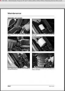
INSTALLING AIR CLEANER
1. Place the air cleaner into the frame; then connect the crankcase breather hose.
2. Secure the carburettor boot to the air cleaner.
3. Install the machine screws securing the air cleaner to the frame.
4. Install the filter with foam wrap into the air cleaner; then secure with the retainer.
5. Install the air cleaner housing cover and secure with the machine screws.
6. Install the ail-intake snorkel.
7. Install the seat making sure it is properly secured

Posted on

AGCO/Massey-Ferguson Telescopic Handler MF 8925/8926/8947 Factory Service & Shop Manual

Pages from AGCO-Massey-Ferguson Telescopic Handler MF 8925-8926 Workshop Service Manual

MMF8900OPES.zip
Price: $29.99 USD

Complete workshop & service manual with electrical wiring diagrams for AGCO/Massey-Ferguson Telescopic Handler MF 8925, 8926, 8947. It’s the same service manual used by dealers that guaranteed to be fully functional and intact without any missing page.

This AGCO/Massey-Ferguson Telescopic Handler MF 8925/8926/8947 service & repair manual (including maintenance, overhaul, disassembling & assembling, adjustment, tune-up, operation, inspecting, diagnostic & troubleshooting…) is divided into different sections. Each section covers a specific component or system with detailed illustrations. A table of contents is placed at the beginning of each section. Pages are easily found by category, and each page is expandable for great detail. The printer-ready PDF documents work like a charm on all kinds of devices.

FILELIST:
AGCO/Massey-Ferguson Telescopic Handler MF 8925/8926 Workshop Service Manual.pdf
AGCO/Massey-Ferguson Telescopic Handler MF 8947 Workshop Service Manual.pdf

EXCERPT:
CONTENTS
FOREWORD. . . . . .ii
SAFETY INSTRUCTIONS . . . . .v
SERIAL NUMBER LOCATIONS. . . . . . vii
DELIVERY REPORT . . . . . viii
TELESCOPIC HANDLER IDENTIFICATION . . . . . viii
SAFETY MAINTENANCE . . . . . 10-01
HYDRAULIC SYSTEM . . . . . . 20-01
HYDROSTATIC SYSTEM . . . . . . 30-01
DRIVE SYSTEM . . . . . 40-01
MAIN FRAME . . . . . 50-01
ELECTRICAL SYSTEM & ANALYSIS . . . . . . 60-01
ENGINE SERVICE . . . . . 70-01
HEATING, VENTILATION, AIR CONDITIONING . . . . . . 80-01
SPECIFICATIONS . . . . . . SPEC-01

AXLE AND DIFFERENTIAL (FRONT) (CONT’D)
Planetary Carrier Disassembly (Cont’d)
Figure 40-20-8
Remove the thrust washers (Item 1) [Figure 40-20-8] from each shaft.